Hv Transformer Diagram

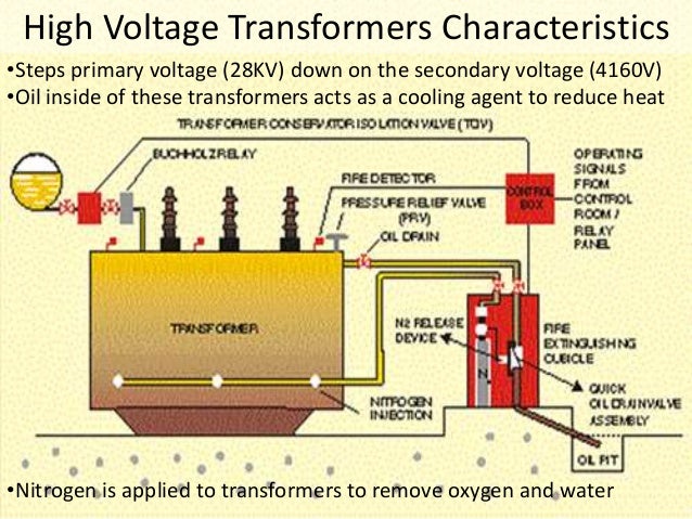
High Voltage Transformers Electrical4u

Three Phase Transformer Connections And Basics

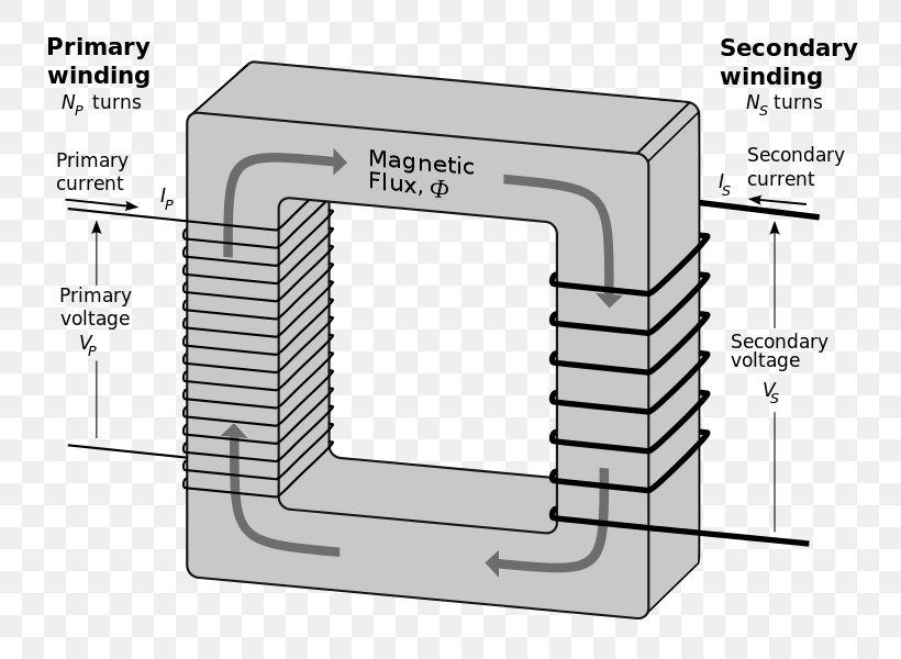
Transformer Basics And Transformer Principles
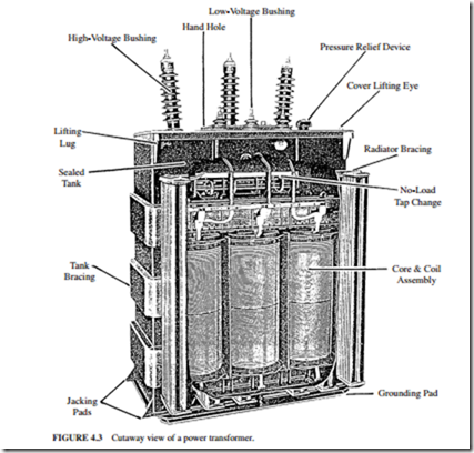
Transformer Components And Maintenance Main Components Of A Power Transformer Electric Equipment

Transformer Parts Electrical Engineering Books Electrical Engineering Books Power Engineering Electrical Transformers

Step Down Transformer Definition Diagram Working Principle Electrical4u
The four basic connections are.
Hv transformer diagram. 30 behind of the zero hour position of the hv line phasors. The direction of i a relative to that of i a must honor the dot convention. The first symbol indicates the connection of the primary and the second symbol is the. Share your answer in the comments section below.
Microwave transformers use one of the hv leads connected to the transformer case which is earth ground in a microwave. Such transformers are designed to have an inherently good voltage regulation which is possible by arranging the coils in such a way as to have minimum leakage reactance. Read about how vector groups are used in setting up a transformer differential protection. Use many 10w or higher to total 300 000 ohms which limits the current to 5ma 1500v 5ma 300 000 ohms.
Such transformers have percentage impedance of 4 5 and voltage regulation of 4 8. A poly phase transformer with hv winding in delta lv winding in star with neural and the lv line phasor 1 o clock i e. 1 3 i l of the line current where i l is the line current. The high voltage phase current corresponding to i a is labeled i a.
To limit this current a high resistance is connected in series with transformer. When analyzing a transformer using per unit n 1 so it becomes. The magnitude of i a relative to i a is the inverse of the transformer turns ratio n or. For insulator testing purposes the required current is very less but while the insulator breaks down during testing there would flow huge current through the transformer.
In a delta connected dd group of transformers the line voltage v l is equal to the supply voltage v l v s but the current in each phase winding is given as. A dyn11 for example indicates that the lv leads the hv by 30 therefore the hv winding should be dac connected. Can you determine the vector group of the configuration shown in figure 1. As shown in the above figure the transformer is having 3 phases on hv side 1u 1v 1w and 3 phases on lv side 2u 2v 2w.
I a i a. So i a i a. The distribution transformers are usually 3 phase 4 wire 11 kv 415 v delta star connected. Y y y y and.
One disadvantage of delta connected three phase transformers is that each transformer must be wound for the full line voltage in our example above 100v and for. When a single unit or bank of three is used there are four types of connections.
25 High Voltage Transformer Tests And Commissioning Procedures Before Energizing Eep

Bushing Of Transformer For H V Side And L V Side Electricalunits Com

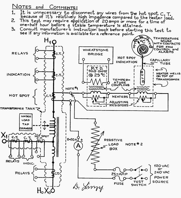
Schematic Diagram For Testing Hv Winding Of Resonating Transformer At Download Scientific Diagram

Cup0ybi5ldjzcm

Wiring Diagram Current Transformer Three Phase Electric Power High Voltage Transformer Angle Rectangle Png Pngegg
High Voltage Transformer

Circuit Diagram For Generating High Frequency High Voltage From Flyback Download Scientific Diagram

Transistor Driven High Voltage Flyback Transformer Page
Power Distribution 2 Docx
Oscillator For High Voltage Transformer Rlc Or Blocking Oscillator Electrical Engineering Stack Exchange

5 A Schematic Of The Pd Measurement System With A High Voltage Download Scientific Diagram

20kv Dc High Voltage Flyback Power Supply Circuit Power Supply Circuit Electronic Circuit Projects Power Supply

Charging A Capacitor At High Voltage Electrical Engineering Stack Exchange