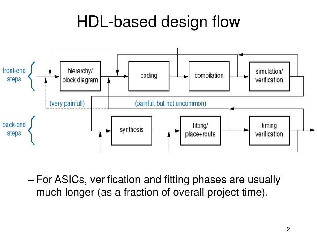
Hdl Based Design Flow
Design Flow And Methodology

Design Flow And Methodology
Design Flow And Methodology
Design Flow And Methodology
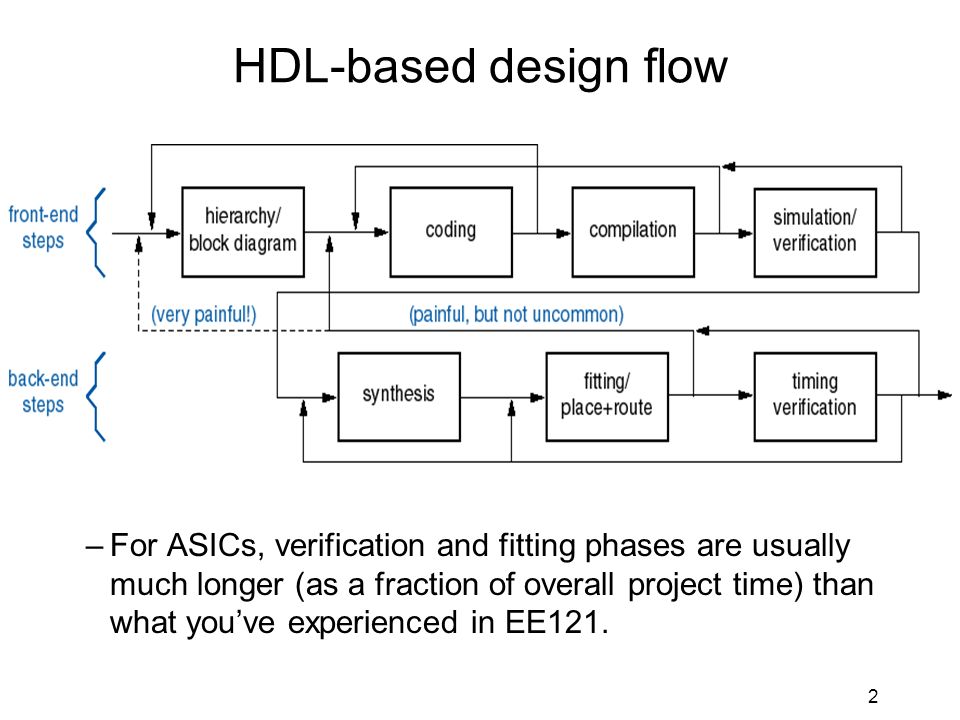
Ee121 John Wakerly Lecture 17 Ppt Video Online Download
Proposed Design Flow From Hdl And Hls Highlighting The Additional Download Scientific Diagram
When the design is complex or the designer thinks the design in an algorithmic way then hdl is the better choice.
Hdl based design flow. The use of flow based design tools allows for more holistic system design and faster development. Like concurrent programming languages hdl syntax and semantics include explicit notations for expressing concurrency however in contrast to most software programming languages hdls also include an explicit notion of time which is a primary attribute of hardware. The use of flow based design tools in engineering is a reasonably new trend. Hdl based approaches on the other hand tend to be fast and easy to implement and today is most popular design entry for fpga designs.
Hierarchical modeling concepts top down and bottom up design methodology differences between modules and module instances parts of a simulation design block stimulus block. If the designer wants to deal more with hardware then schematic entry is the better choice. Generating hdl code directly from these models lets you adapt to changes and it maintains traceability between the vhdl or. C to hdl tools and flow have a similar aim but with c or c like programming languages.
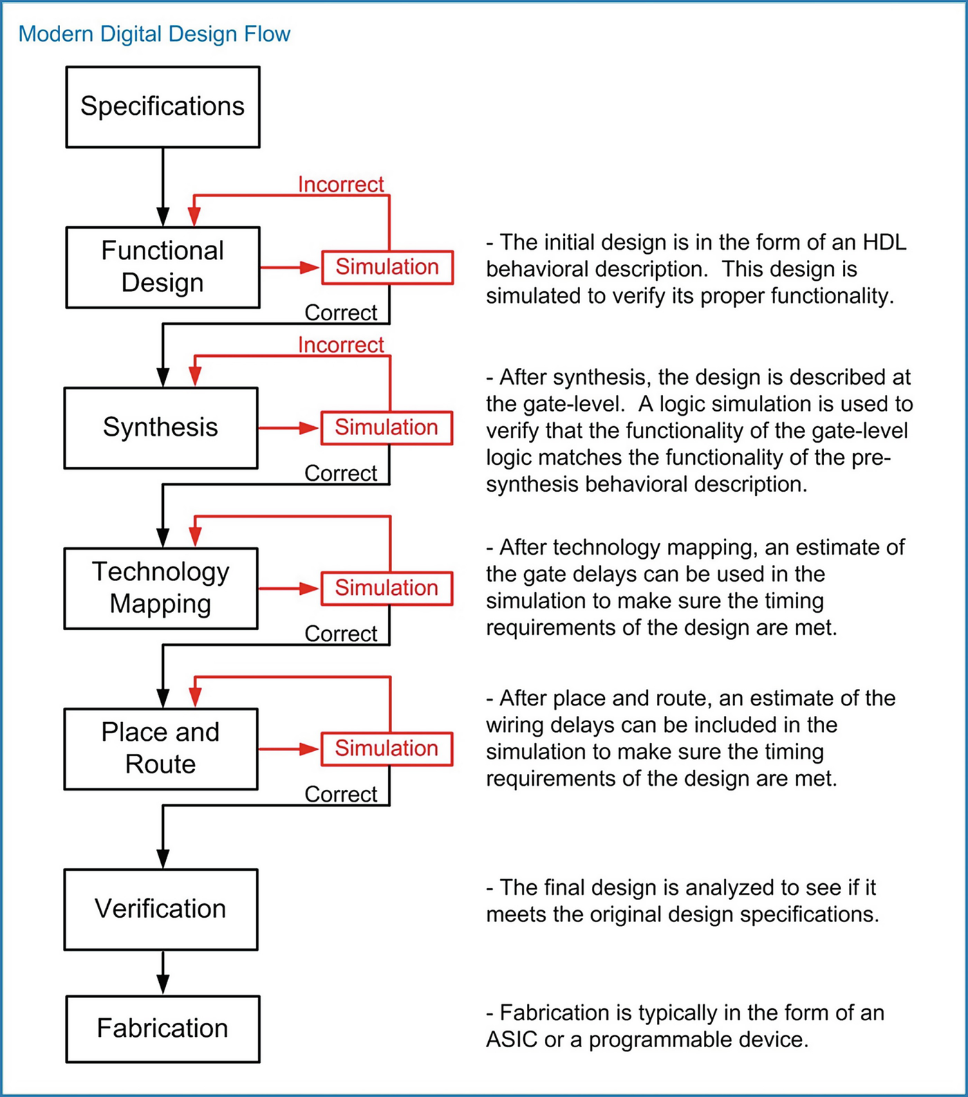
Synthesis after the design has been entered in the form of code this phase is where it is translated into an actual circuit with elements such as gates flip flops and multipliers among others. With simulink algorithm developers can collaborate with hardware software and analog design engineers. They are later used to ensure that the hdl description of a device is correct. Overview of digital design with verilog hdl evolution of cad emergence of hdls typical hdl based design flow why verilog hdl trends in hdls.
The most common hdls are vhdl and verilog. This is specially designed for the pre final and final year engineering students to start learning the vlsi fundamentals while doing their engineering itself. Unified modeling language is the most widely used example for software design. Schematic based hardware description language and combination of both etc.
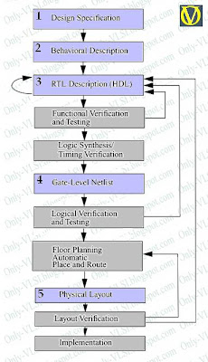
The device is described in a formal hardware description language hdl. ø design entry and synthesis. Dtek8067 hdl based design 5 ects dtek8067 hdl based design 5 ects. This stage involves writing of test environments and behavioral models when applicable.
Simulation as a verification method and the creation of testbenches for simulations. They can use the same models to design explore tradeoffs and verify the system architecture before beginning implementation. Synthesizable vhdl synthesis process and constraining for synthesis. Xilinx synthesis technology xst gui can be used to synthesize the hdl file into an ngc file.
In this step of the design flow design is created using a a hardware description language hdl for text based entry.
Https Ashwinjs Files Wordpress Com 2018 01 Unit 3 Q A Pdf
Design Flow And Methodology
Introduction To Verilog Hdl
Vhdl Based Design

Fpga Implementation Step By Step Digital System Design

7 Design Flow Of Filter Design Hdl Coder Toolbox Download Scientific Diagram
Ppt Digital Design I Dr M Marouf Introduction To Vhdl Powerpoint Presentation Id 5249260

Ise Design Flow Overview
Design Flow And Methodology

Fpga Design Flow Overview Fpga Central

Cal To Hdl Design Flow With The Proposed Cal To Cal Pipeline Download Scientific Diagram
Design And Tool Flow
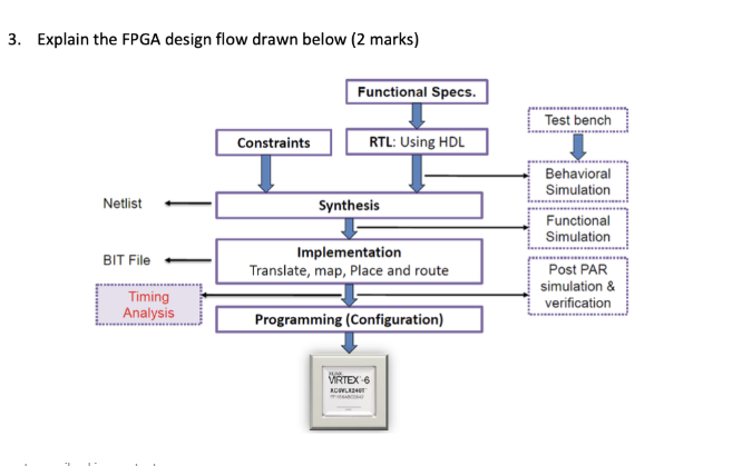
Solved 3 Explain The Fpga Design Flow Drawn Below 2 Mar Chegg Com